![[C# Helper]](../banner260x75.png)
|
|
 |
![[Beginning Database Design Solutions, Second Edition]](db2_79x100.png)
![[Beginning Software Engineering, Second Edition]](book_sw_eng2_79x100.png)
![[Essential Algorithms, Second Edition]](book_algs2e_79x100.png)
![[The Modern C# Challenge]](book_csharp_challenge_80x100.jpg)
![[WPF 3d, Three-Dimensional Graphics with WPF and C#]](book_wpf3d_80x100.png)
![[The C# Helper Top 100]](book_top100_80x100.png)
![[Interview Puzzles Dissected]](book_interview_puzzles_80x100.png)
![[C# 24-Hour Trainer]](book_csharp24hr_2e_79x100.jpg)
![[C# 5.0 Programmer's Reference]](book_csharp_prog_ref_80x100.png)
![[MCSD Certification Toolkit (Exam 70-483): Programming in C#]](book_c_cert_80x100.jpg)

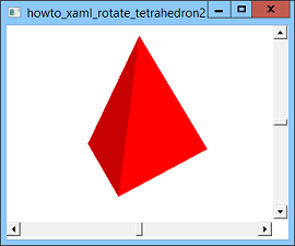
Title: Rotate a tetrahedron with crisp edges using XAML and C#
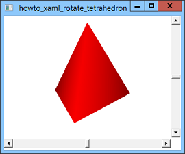
This example modifies the post Rotate a tetrahedron using XAML and C# to draw and rotate a tetrahedron with crisp edges. The previous example is shown in the second picture above. Notice that the edge between the tetrahedron's two front-facing sides is blurry, so you really can't tell where one side ends and the other begins. The reason this happens is because of the lighting model used by WPF. That example uses the following XAML code to define its light sources.
<AmbientLight Color="Gray" /> <DirectionalLight Color="LightGray" Direction="-1,-2,-3" /> This code defines two light sources. The first represents ambient light that fills the scene. Ambient light is uniform sourceless illumination that comes from everywhere. It's basically the reason you can see something under a table even though there are no sunlight, lamps, or other light sources shining there. If you take a look under your desk now, you'll probably notice that everything under there receives roughly the same amount of light (depending a bit on how far an object is from the edge of the desk). The second light is directional. It represents a light source shining in the direction <-1, -2, -3>. The amount of light that this source contributes to a surface depends in large part on the angle the light makes when it strikes the surface. For example, if you place a piece of paper under a lamp so the light strikes it at a direct 90 degree angle, the paper looks bright white. If you tilt the paper so the light strikes it from a small angle, the paper looks gray. (Give it a try.) WPF calculates the angle between the light source and the surface by using the light's direction and the surface's normal, a vector with length 1 that points perpendicularly out of the surface. WPF stores surface normal information for each of the points in its data model. For the previous example, that means the program stores a normal vector for each of the four vertices that make up the tetrahedron. If you think about what that means, you may be able to see the problem. Each vertex is part of three triangles, each of which is oriented in a different direction. If the three triangles have different orientations, how can they all have the same normal at their common point? Of course the answer is they can't. Because the program's data didn't explicitly indicate the normal at that shared point, WPF calculated a normal by averaging the normals of all of the triangles that contain that point. The result is a normal that doesn't really fit any of the triangles. WPF colors the points on each triangle to blend the colors given by the triangle's three corners. Because adjacent triangles share corners, they also share normals at their corners, so they have the same colors at those corners. (The same applies to their edges.) The result is the fuzzy picture shown above. So what can you do about this? As I mentioned above, the triangles cannot have correct normals at their corners if they share corners. The solution is to make the triangles not share corners. WPF calculates each vertex's normal based on the triangles that contain it. Because each vertex is contained in a single triangle, WPF gives each vertex the correct normal for its triangle. (You can also explicitly specify a normal for each vertex, but for objects defined by flat surfaces such as this one, it's easier to let WPF do it for you.) The following code shows how the new example defines its triangles.
<MeshGeometry3D Positions=" 0, 0, 1.15470053837925150, 1, 0, -0.57735026918962584, 0, 1.6329931618554521, 0, 1, 0, -0.57735026918962584, -1, 0, -0.57735026918962584, 0, 1.6329931618554521, 0, -1, 0, -0.57735026918962584, 0, 0, 1.15470053837925150, 0, 1.6329931618554521, 0, 0, 0, 1.15470053837925150, -1, 0, -0.57735026918962584, 1, 0, -0.57735026918962584 " TriangleIndices=" 0 1 2 3 4 5 6 7 8 9 10 11 " /> The tetrahedron has only 4 vertices but this code defines 12 points, 3 for each triangle. Each point is repeated 3 times, once for each of the triangles that contains it. The result is shown in the first picture above. If you are making a smoothly shaded surface such as a relief map, sphere, or torus, you may want to have triangles share vertices so the program shades them smoothly. If you want sharply defined edges between triangles, you should repeat vertices as needed so the triangles don't need to share them. Download the example to experiment with it and to see additional details. |