![[C# Helper]](../banner260x75.png)
|
|
 |
![[Beginning Database Design Solutions, Second Edition]](db2_79x100.png)
![[Beginning Software Engineering, Second Edition]](book_sw_eng2_79x100.png)
![[Essential Algorithms, Second Edition]](book_algs2e_79x100.png)
![[The Modern C# Challenge]](book_csharp_challenge_80x100.jpg)
![[WPF 3d, Three-Dimensional Graphics with WPF and C#]](book_wpf3d_80x100.png)
![[The C# Helper Top 100]](book_top100_80x100.png)
![[Interview Puzzles Dissected]](book_interview_puzzles_80x100.png)
![[C# 24-Hour Trainer]](book_csharp24hr_2e_79x100.jpg)
![[C# 5.0 Programmer's Reference]](book_csharp_prog_ref_80x100.png)
![[MCSD Certification Toolkit (Exam 70-483): Programming in C#]](book_c_cert_80x100.jpg)

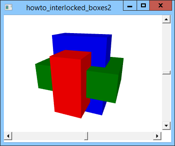
Title: Use static resources to draw three interlocked boxes using XAML and C#
This example modifies the example Draw three interlocked boxes using XAML and C# to use static resources to draw three interlocked boxes. The previous example draws three cubes and then scales them to make them interlock. One problem with this technique is that it requires you to include three identical copies of the data that defines the cubes. That means you need to write, debug, and maintain the code in three places. The following code shows how the program defines its red box. The code in blue is duplicated for all three boxes.
<GeometryModel3D> <GeometryModel3D.Geometry> <!-- Cube --> <MeshGeometry3D Positions=" -1,-1,-1 1,-1,-1 1,-1, 1 -1,-1, 1 -1,-1, 1 1,-1, 1 1, 1, 1 -1, 1, 1 1,-1, 1 1,-1,-1 1, 1,-1 1, 1, 1 1, 1, 1 1, 1,-1 -1, 1,-1 -1, 1, 1 -1,-1, 1 -1, 1, 1 -1, 1,-1 -1,-1,-1 -1,-1,-1 -1, 1,-1 1, 1,-1 1,-1,-1 " TriangleIndices=" 0 1 2 2 3 0 4 5 6 6 7 4 8 9 10 10 11 8 12 13 14 14 15 12 16 17 18 18 19 16 20 21 22 22 23 20 " /> </GeometryModel3D.Geometry> <GeometryModel3D.Transform> <ScaleTransform3D ScaleX="1" ScaleY="2" ScaleZ="3" /> </GeometryModel3D.Transform> <GeometryModel3D.Material> <DiffuseMaterial Brush="Red" /> </GeometryModel3D.Material> </GeometryModel3D> You can reduce the amount of duplicated code if you define static resources to hold the common data. To do that, you can add a Resources section to just about any object in the XAML code. This example adds it to the main Window object, so the resources are available everywhere in the file. The following code shows how the program defines the cube point and triangle data. The Resources section is shown in blue.
<Window x:Class="howto_interlocked_boxes2.Window1" xmlns="http://schemas.microsoft.com/winfx/2006/xaml/presentation" xmlns:x="http://schemas.microsoft.com/winfx/2006/xaml" Title="howto_interlocked_boxes" Height="300" Width="300"> <Window.Resources> <!-- Define points representing a cube. --> <Point3DCollection x:Key="CubePoints"> -1,-1,-1 1,-1,-1 1,-1, 1 -1,-1, 1 -1,-1, 1 1,-1, 1 1, 1, 1 -1, 1, 1 1,-1, 1 1,-1,-1 1, 1,-1 1, 1, 1 1, 1, 1 1, 1,-1 -1, 1,-1 -1, 1, 1 -1,-1, 1 -1, 1, 1 -1, 1,-1 -1,-1,-1 -1,-1,-1 -1, 1,-1 1, 1,-1 1,-1,-1 </Point3DCollection> <!-- Define triangles representing a cube. --> <Int32Collection x:Key="CubeTriangles"> 0 1 2 2 3 0 4 5 6 6 7 4 8 9 10 10 11 8 12 13 14 14 15 12 16 17 18 18 19 16 20 21 22 22 23 20 </Int32Collection> </Window.Resources> <Grid> ... </Grid> </Window> The first resource is a Point3DCollection (a collection of Point3D objects) named CubePoints. It defines the vertices for the cube. The second resources is an Int32Collection (a collection of 32-bit integers) named CubeTriangles. It contains the indices of the points that make up the cube's triangles. Now the code that defines the boxes can refer to these resources instead of including all of the vertex and triangle data. The following code shows how the program defines the red box. The blue code refers to the resources.
<!-- Red box --> <GeometryModel3D> <GeometryModel3D.Geometry> <!-- Cube --> <MeshGeometry3D Positions="{StaticResource CubePoints}" TriangleIndices="{StaticResource CubeTriangles}" /> </GeometryModel3D.Geometry> <GeometryModel3D.Transform> <ScaleTransform3D ScaleX="1" ScaleY="2" ScaleZ="3" /> </GeometryModel3D.Transform> <GeometryModel3D.Material> <DiffuseMaterial Brush="Red" /> </GeometryModel3D.Material> </GeometryModel3D> This code uses the StaticResource statement to refer to the common resources. The rest of this code is different for the three boxes. You can actually go a little farther with static resources. All three boxes define a MeshGeometry3D object that uses the cube vertices and positions. This example actually includes the following resource code inside the Window's Resources section to define a MeshGeometry3D object named CubeGeometry.
<!-- Define the vertices and triangles for a cube. --> <MeshGeometry3D x:Key="CubeGeometry" Positions="{StaticResource CubePoints}" TriangleIndices="{StaticResource CubeTriangles}" /> This code uses the previously defined CubePoints and CubeTriangles resources to create a MeshGeometry3D object that defines a cube. The following code shows how the example uses that object to create the blue box. The code that defines the cube is shown in blue.
<!-- Blue box --> <GeometryModel3D Geometry="{StaticResource CubeGeometry}"> <GeometryModel3D.Transform> <ScaleTransform3D ScaleX="2" ScaleY="3" ScaleZ="1" /> </GeometryModel3D.Transform> <GeometryModel3D.Material> <DiffuseMaterial Brush=" Blue" /> </GeometryModel3D.Material> </GeometryModel3D> This lets the three boxes share just about as many resources as they can. Now if you decide to modify the basic cube, for example by moving the vertices or changing their coordinates from all 1s to all 2s, you only need to do it in one place. Download the example to experiment with it and to see additional details. |